the pre-prehistory
as a computer programmer of a certain age, who originally went from “guy who likes computers” to “guy who likes computers way too much” through the turn-of-the-millennium Linux/open source community, at one point I read through the Jargon File and developed a casual obsession with the computers and “hacker culture” of the ’60s and ’70s, and particularly the Digital Electronics Corporation (DEC) PDP-11, the minicomputer which gave birth to Unix.
I had gotten into computers as a kid precisely because I grew up poor (I was using a hand-me-down PS/2 Model 30 until about the turn of the millennium) and software was a realm to experiment with, and make mistakes in, where making things didn’t have to cost money if you had enough time to throw at it. aside from a couple hardware classes in college, I basically didn’t touch hardware design at all until after I graduated — and even in those hardware classes, we mostly just assembled 7400-series chips in solderless breadboards and programmed PLDs.
but in 2018, Oscar Vermeulen released the PiDP-11, a custom case for the Raspberry Pi which is a scale replica of the PDP-11 processor’s front panel, which allows you to have the full minicomputer experience of keying in a bootloader by hand, examining memory, etc., while requiring about 99.5% less power and floor space. since the PiDP-11 was only sold as a kit, I decided this would be the project that would teach me to solder, and learning that I had been terrified of soldering for absolutely no reason removed the one obstacle that stood in the way of me picking up hardware as a hobby.
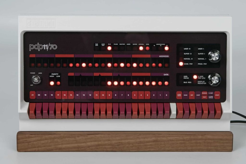
the birth of the project
the PDP-11 was launched in 1970, and the processor was implemented with about a dozen big circuit boards full of discrete 7400-series logic chips, but the PDP-11 was relevant long into the large-scale integration era, so in the early ’80s, DEC designed a single-chip LSI version of the processor, the J-11, which was integrated into the “MicroPDP-11”, a microcomputer available in basically modern desktop form factors.
I knew that J-11s were out there on ebay, but I figured that they were only useful for spares or a desktop trinket. but for whatever reason I was browsing bitsavers one night earlier this year, and discovered that they had DEC’s semiconductor data books from the late ’80s, which contain complete enough datasheets for the J-11 that, coupled with other folks’ prior art, made me confident that I could actually use one for a practical purpose.
so, pretty much on a whim, I decided to embark on a project to build a new computer with Raspberry Pi-compatible GPIO, in a form factor that I could fit inside the PiDP-11 chassis, using a real J-11 as a processor and an FPGA to provide glue logic and simulate peripherals like a serial card and storage controller.
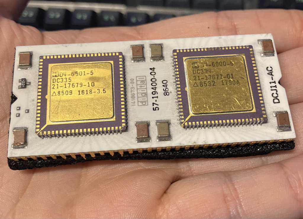
the birth of the side project
unfortunately, after buying the J-11, I discovered that, while it behaves like an old PDP-11 in most respects I cared about, there was no front panel to drive on the MicroPDP, and so DEC hadn’t bothered to make the J-11 implement the front panel I/O, in favor of the serial port-based Console ODT.
not wanting the money I’d already spent on parts (about $60, a princely sum) to be wasted, I decided to change goals to making a small scale replica of a MicroPDP to sit on a desk. needing a serial terminal to debug the computer I was going to build anyway, and also wanting a simpler, lower-stakes side project to actually get good at hardware design with, I also decided to start by designing a little microcontroller-powered semi-scale replica of the DEC VT100, the ’57 Chevy of terminals. (I know it’s anachronistic to connect a VT100 to a MicroPDP. but the VT2/3/4xx series looked so boring.)
requirements and goals
- an RS-232 compatible serial port. I wanted this mostly because I miss D-sub connectors, but I decided to go with DE-9 instead of DB-25 because I’m only kinda committed to the bit.
- a keyboard. because I didn’t want to start a second-order side project and I wanted the keyboard to be at least kind of in-scale, I decided that this meant Bluetooth support, and a garbage-y, cheap $10 Bluetooth phone keyboard (at least until I go back and do that second-order side project.)
- an integrated LCD screen. a reasonable 80×24 terminal requires a screen at least 640 pixels wide, and the smallest 640×480 resolution screens I could find in small quantities on display market sites were 3.5″ diagonal, so I decided to go with those and set the scale of the whole project at about 3.5:1. the part I ended up choosing was the EastRising ER-TFT035-7, without a touch panel.
- the cheapest, simplest microcontroller feasible, so the project actually requires me to work for it.
- minimum requirements for video: 80×24 character mode; green, amber, and white, plus ANSI color as a stretch goal.
hardware revision A (fabrication date: late july)
I designed this revision to use the Raspberry Pi Pico W as a microcontroller dev board, which has a Raspberry Pi RP2040 and a Cypress/Infineon CYW43439 Bluetooth controller. the limiting factor in this design was GPIOs — the RP2040 only has 29 of them, ruling out full 24-bit color almost immediately. the Pico W reserves three of them to communicate with the Bluetooth chip, you need to burn another six on the RS-232 port, and the serial command interface for the display requires 8 pins, so I was resigned to supporting a single 16-color palette, stored in a comically small part of a 64Kx16 palette RAM with an I2C I/O expander.
I made a couple really careless design mistakes in this revision:
- the board took 5V power input via USB-C, and ran most of the electronics off of 3.3V. unfortunately, I failed to notice that in a late design revision, I had screwed up the priority on some of the copper pours on the board, and the switching node of the 3.3V supply no longer had a copper pour on it, so it didn’t work. this was easy enough to fix by just not placing any of the power supply components, and soldering a buck converter module I already had lying around onto some test points.
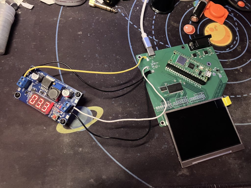
- the pin assignments for the RS-232 port and LCD SPI interface were completely incorrect for the RP2040’s hardware peripherals, and had to be bodged after the fact. this was a fucking nightmare because I had to solder bodge wires directly to the legs of the RS-232 drivers.
- luckily, it actually didn’t end up mattering that the SPI pinouts were incorrect for the RP2040’s hardware SPI peripheral, because the command interface to the screen that the datasheet calls “SPI” doesn’t actually use any of the standard flavors of SPI, and I had to bit-bang it anyway.


- foolishly, I overlooked that I was using 5V-only RS-232 drivers (the TI MAX202) on a 3.3-volt microcontroller. the board I assembled lasted for a few hours before enough of the RP2040 cooked itself for it to no longer boot, but only a few. I basically didn’t get to test the LCD interface on this rev A at all because of this.
hardware revision B (fabrication date: mid-august)
even without the 5V/3.3V mixup, working with revision A was really annoying, because proving that you can get the screen working requires not just getting the serial command interface working, it also requires getting enough of the parallel data interface (sync signals + framebuffer) working that you can display a color other than black. to hopefully skip over a few steps, I decided to build a revision of the board to fit as a shield on top of a Nucleo development board for the ST STM32F439ZI microcontroller, which has an integrated LCD controller hardware peripheral that I hoped would let me quickly prove out controlling the screen on a firmware level.
and it did!
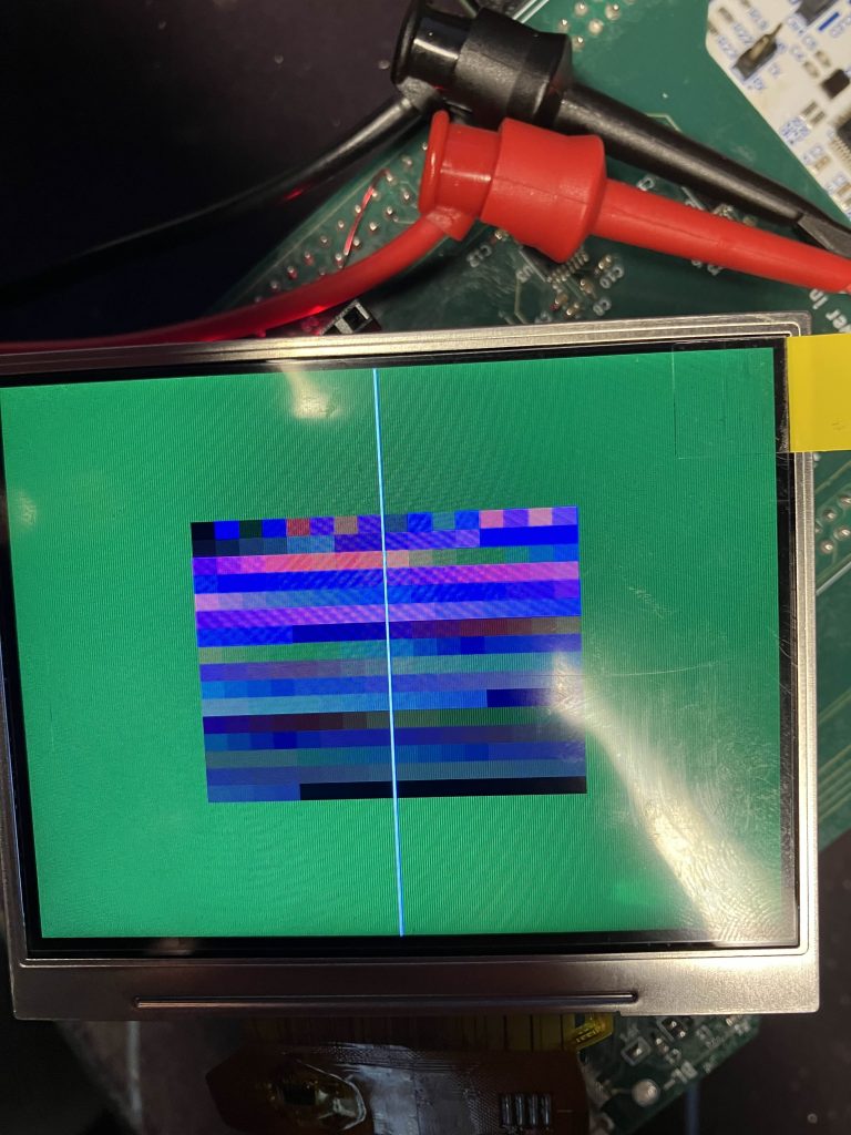
STM32s don’t have an integrated Bluetooth controller (except for the STM32WB, apparently), so I went with what I thought would be an easy “nobody ever got fired for buying IBM”-style choice: the Espressif ESP32, now available in RISC-V as the ESP32-S3.
what a fool I was. the ESP32-S3’s promotional web site says it does “Bluetooth 5.0 (LE)”. naively I assumed this meant “Bluetooth 5.0, and also Bluetooth Low Energy”. it doesn’t — I unthinkingly bought a Bluetooth Classic phone keyboard because it was $10 and didn’t fully understand the difference between Classic and LE, and then discovered that it was completely invisible to my ESP32-S3. I could’ve probably just bought a Bluetooth Low Energy keyboard, but instead I fixed this issue by buying an ESP32 (no -S3) development kit, and building a janky interposer on perfboard to make it pin-compatible with the ESP32-S3 dev kit I had designed this board for. that was enough to verify that I could connect to the keyboard from this ESP32, receive keypress events, and send data over the UART.
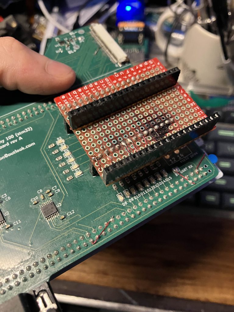
going into this project, I had assumed that basically every project that had an application microcontroller and a separate Bluetooth microcontroller was using the Bluetooth chip as a dumb serial port, and inventing some sort of custom command language for scanning/pairing/etc. thankfully, the truth is that there’s a standardized protocol called the Bluetooth Host Controller Interface which a Bluetooth host and Bluetooth controller chip can use to speak to one another.
unfortunately, the HCI is complex enough that the specification runs to more than 1,000 pages (and requires you to be a paying member of the Bluetooth SIG to read it in the first place), and there are only about three off-the-shelf embedded HCI host implementations; one of them has no Bluetooth Classic support, and one of them has “limited” Bluetooth Classic support, so that leaves one to mess around with. the HCI also (generally) requires hardware flow control pins that I hadn’t punched through, and I already knew I needed to spin a Rev C board, so I wasn’t too keen to bodge them and then bodge them again on the interposer, and I left the exploration there on this hardware revision.
lessons learned so far
- there’s all sorts of checks you should make before spinning a board of any complexity, and I would’ve caught a lot of issues in Rev A if I’d remembered to make them.
- I’ve taken to pasting images of the RP2xxx GPIO assignment matrix directly into the schematic alongside the symbol, and double-checking that there are no conflicts before sending out the production files.
- always remember, before you save Gerbers, even if you think you already have:
- make sure the status bar at the bottom of KiCad says “unrouted: 0”;
- run ERC and DRC, and make sure you can explain to yourself why every error and warning there is left.
- I really liked this youtube video from “Cosplay Light and Sound”, and picked up a few new good habits from it:
- designing in test hook attachment points even if I don’t end up populating them;
- designing in isolation jumpers for power supplies, and to give me added bodge points on buses;
- designing in LEDs and test points for unused GPIOs.
- I decided to use an LCD with a parallel interface instead of one with a MIPI DSI interface because I thought it would save me a lot of grief dealing with high-speed signaling. I’m not sure this was a good idea in retrospect, because I probably could’ve chosen an off-the-shelf MIPI DSI controller, followed the application section in the datasheet, and been done with this project a couple months ago.
- tools and supplies that I think should be in your electronics toolkit if you’re planning on designing PCBs:
- a cheap electric engraving pen. this is useful for two things: abrading solder mask, so you can solder directly to traces on a board; and cutting through traces for isolation more reliably and more precisely than cutting through them with the tip of a knife blade. I think I learned about the uses of these for electronics rework from Adrian of Adrian’s Digital Basement.
- fine-gauge magnet wire; I use 28 AWG, which is good for somewhere between 200mA and 2.4A, depending on who you ask, which is honestly way more than I ever actually need it to carry. this stuff is great for bodges. it’s insulated, and you can strip it in the ends or in the middle; you can solidly solder it down to 0.35mm traces, and in a pinch it’s good down to 0.2mm. it doesn’t always save you from your own bad board designs, but it does a lot of the time.
- man the STM32 software and tools ecosystem is annoying.
- when you’re doing a design with a microcontroller you need to have pin assignments chosen for all your peripherals before you can send out the board for fabrication; you can’t move wires around after you get a finished board in the mail.
- coming up with pin assignments is easy enough to do by hand with RP2xxx microcontrollers, because basically every pin can connect to every peripheral, but you can’t do this with STM32 chips; each peripheral’s inputs and outputs can only connect to one or two pins on the package, and there are all sorts of abstruse dependencies between the settings you choose on any one of those peripherals and the other peripherals available to you. (want 24-bit color and an external memory controller at the same time? sorry, you needed to have chosen a chip in a 176-pin package when you started the project, even though 100 of your I/O pins are still unassigned.)
- the tool you use to generate your pin assignments (STM32CubeMX) doesn’t really seem to give you a good way of “window shopping” for an STM32 that meets your design requirements, because it doesn’t make it easy to change your target chip after you create a project.
- the standard workflow also requires you to make configuration choices for the microcontroller’s peripherals in the project generator, and then auto-generates you some very long, clunky C++ files that you can put user code into specific sections of. want to change the background color of the display controller output? you have to regenerate the entire project. want to set the framebuffer base address register of the controller to a non-constant value? you need to do it by hand in your user code.
- in spite of this, the STM32 LTDC probably did save me dozens of hours of firmware development. so it’s not all bad.
- I’m glad that the Nucleo boards exist, but they make very opinionated choices about what peripherals you’re going to use on the STM32 chip. to free up all the pins I needed to use the LTDC on a Nucleo board, I had to lift almost a dozen jumpers that came preinstalled from the factory. I get it, ST, you want to showcase that you have this $7 part that does Ethernet, but it’s an annoying little extra step to have to go hunting around a development board for stuff to desolder just to be able to use peripherals which are locked out from the factory.
- Bluetooth is a nightmare.
- BuyDisplay recommends using the PowTech PT4110 backlight driver for this screen, but there are no resellers other than BuyDisplay for this chip in the US so I took a chance on the Diodes Incorporated AP5724, which looked like it would work just fine and, indeed, did turn out to work just fine.
teaser for the next post
the STM32F439ZI only has 256KB of RAM, and even a 640x480x8 framebuffer takes 300KB to store. that means I was only able to ever test the LTDC with a 320×200 image. so I was already planning on spinning a Rev. C with either a different STM32 (I was looking at the STM32H7), or external RAM.
and then this happened.
Leave a Reply